Time:2024-11-28 Views:0

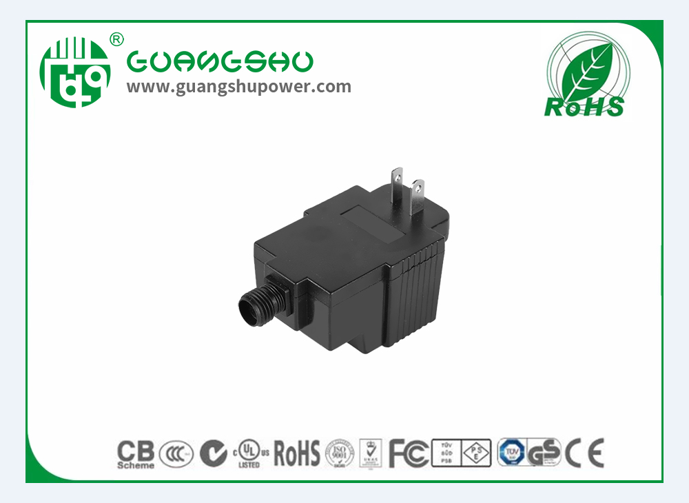
The structure of a power adapter typically consists of several key components. The input stage includes a plug for connecting to the power source, usually an AC wall outlet. This is followed by a fuse, which is a safety device that protects the adapter from excessive current. If the current exceeds a certain level, the fuse will blow, preventing damage to the internal components. Next is the rectifier circuit, which is mainly composed of diodes. The rectifier converts the alternating current (AC) input into a pulsating direct current (DC). A common type is the bridge rectifier, which uses four diodes arranged in a specific configuration.
After the rectifier, there is a filter circuit. The filter circuit is used to smooth the pulsating DC. It usually consists of capacitors and sometimes inductors. The capacitors store and release electrical energy to reduce the ripple in the output voltage. The filtered DC then passes through a transformer. The transformer is used to step down or step up the voltage depending on the requirements of the device being powered. The core of the transformer is made of a magnetic material such as ferrite or laminated iron, and it is wound with copper wire. The output stage of the power adapter includes a voltage regulator. The voltage regulator ensures that the output voltage is stable and within a certain tolerance. It may be a linear regulator or a switching regulator. Finally, there is a connector at the output end for connecting to the device. The connector can be a barrel connector, a USB connector, or other types depending on the specific application. The printed circuit board (PCB) holds all these components together and provides the electrical connections between them. The PCB is usually made of a non-conductive substrate with copper traces for conducting electricity.
Read recommendations:
12W side plug Australian standard Switching power supply